ACCELERATORS IN SPACE
 |
A plasma ion without an electron,
has a positive charge
to be guided by a magnetic field.
has a positive charge
to be guided by a magnetic field.
Thought Experiment's (TE's) brainstorm is a notional spacecraft which uses a particle accelerator to bring fuel particles to very high speeds. At such velocities, a relatively small mass of exhaust particles could accelerate a larger spaceship at g-force to simulate gravity and gain enormous speeds.
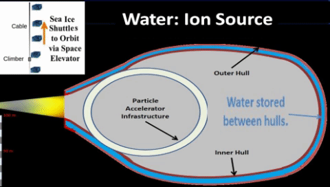
1. PLASMA SOURCES Plasmas are freely moving charged particles, i.e., electrons and ions; plasmas can form at high temperatures when electrons are stripped from neutral atoms. Plasma is by far mass's most common state in nature; stars are predominantly plasma, and stars contain the vast majority of mass in the universe. Due to their charge, ions can be contained and moved by electromagnetic fields. Magnets channel ions into particle accelerators to increase particles' velocity to near light speeds. TE assumes that water can be superheated, gasified, then transformed to plasma, collection of hydrogen(H+) and oxygen(O+) ions or perhaps even hydroxyl(HO+) ions. Plasmas are freely moving charged particles, i.e., electrons and ions; plasmas can form at high temperatures when electrons are stripped from neutral atoms. Plasma is by far mass's most common state in nature; stars are predominantly plasma, and stars contain the vast majority of mass in the universe. Due to their charge, ions can be contained and moved by electromagnetic fields. Magnets channel ions into particle accelerators to increase particles' velocity to near light speeds. TE assumes that water can be superheated, gasified, then transformed to plasma, collection of hydrogen(H+) and oxygen(O+) ions or perhaps even hydroxyl(HO+) ions.As mentioned in previous work, it's very likely that initial g-force vessels will use water supplies exported from Earth's oceans. | ||||||||
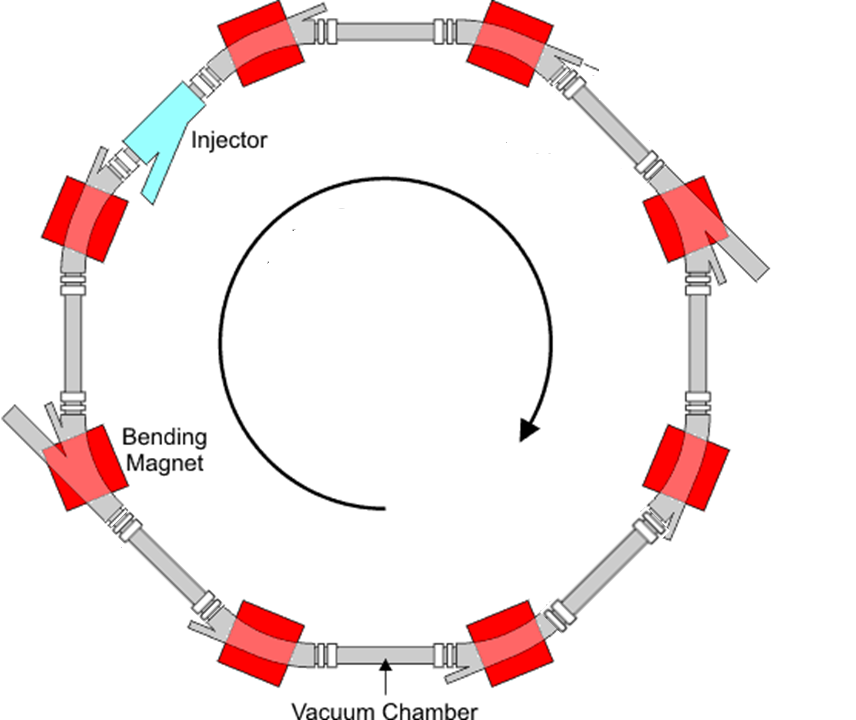
2. PARTICLE INJECTIONInjectors insert water ions into the wave guide. A typical injection process requires three types of magnets: cyclotrons, kickers and septa. A cyclotron has two D-shaped electromagnets (thus, "Dees"). A plasma source emits charged particles at the center of the cyclotron, and the magnetic field bends the ion's path into a constant velocity circle inside the Dees. To accelerate ions, the cyclotron uses a radio wave generator to alternate positive and negative electrical charges between the two Dees. As an ion circles around the cyclotron, it crosses the gap between the two D-shaped cavities. If the charge on the cavity in front of the ion is negative; then, the cavity behind it is positive; thus, the positive ion is compelled to move forward (attracted by the cavity in front and repelled by the cavity behind).  As ions gain speed, their radii increase, and they spiral outwards. With proper timing, the ions always see a negative charge in front and a positive charge behind when it crosses the gap between the Dees. The resultant combination of forces accelerates the ions.
Kicker magnets use pulsed magnets to inject ions into a storage ring. These magnets are driven by a high voltage modulator to produce magnetic fields with very fast rise and fall times (so that the field is only present when the bunch chosen for extraction/injection is passing, and not the previous or subsequent bunches). Timing injection is extremely important as well as beam release and storage duration.
A “septum” separates two field regions (such as an injected beam and the main beam) to provide essential stability for the two beams to gently merge, | ||||||||
| 3. BEAM PIPE PATHWAY | ||||||||
|---|---|---|---|---|---|---|---|---|
| ||||||||
| ||||||||
5. RF CAVITIES
The ideally timed particle will see zero accelerating voltage.
o If particles arrive early; they decelerate to fall back toward the ideal.
o If they arrive late; they accelerate to gain on the ideal particle.
As particles travel the beam pipe for thousands of orbits, they cluster together to form distinct "bunches" about the ideal particles.
Klystrons produce microwaves, electron beams. Thus, beams of negatively charged electrons attract and guide bunches of positively charged ions.Klystrons transmit power via a rectangular waveguide to each RF cavity. Electromagnetic fields are excited in the cavity by coupling in an RF source with an antenna. When the RF frequency fed by the antenna is the same as that of a cavity mode, the resonant fields build to high amplitudes. Charged particles passing through apertures in the cavity are then accelerated by the electric fields and deflected by the magnetic fields.
| ||||||||


6. SUPERCONDUCTION
|
Cable-in-Conduit Conductor (CICC)
CICCs efficiently cool directly from the inside out. Even with tightly packed wires, there remains plenty of room for liquid helium to flow through and provide a low-temperature environment for wires to superconduct.
o CICC magnets quickly turn off/on. Changing magnetic fields produce heat, but CICC magnets can handle heat due to liquid helium immersion of windings.
o CICC magnets are very flexible. They can combine with resistive magnets to form hybrid magnets, together creating a magnetic field that neither the superconducting magnet nor the resistive magnet could achieve alone.
| Wire-Wound (WW) magnets maintain low temperature with 100 layers of insulation.. Completed WW magnet goes inside a cryostat to keep the magnet cold enough to super-conduct. Thus, WW magnets don't need liquid helium inside the cables.
o WW magnets ramp up very slowly to stay cool. With coolant on the outside, internal windings can't handle the heat from a changing magnetic field.
o WW magnets provide an uniform field with no power requirements. After ramp up, WW magnets disconnect power, but superconducting continues for an ultra-smooth current; thus, an ultra-smooth, consistent magnetic field precisely controls particles' path for a very long time.
| |
| Thought Experiment assumes on board accelerators will use both types. However, vast majority of space borne superconducting electro-magnets will be Wire Wound (WW). WW magnet easily maintains same size mag-field. | ||
|---|---|---|
|
Superconducting radio frequency (SRF) technology applies electrical superconductors to radio frequency devices. Minuscule resistance allows SRF resonator to obtain an extremely high quality factor, Q, with very low loss and narrow bandwidth. High Q cavities enable high-performance particle accelerators. SRF cavities' resonant frequency typically ranges from 200 MHz to 3 GHz, depending on the particle species to be accelerated.
Accelerators typically use resonant RF cavities coated with superconducting materials. The most common fabrication technology stamps thin walled (1–3 mm) shell components from pure niobium sheets and then welds these shell components together to form cavities.
SRF cavities gain significant benefits
a) High Duty Cycles. SRF cavities excite electromagnetic fields to much higher levels than possible for resistive cavities; copper cavities would melt at such levels.
b) Larger Particle Beams. The low electrical loss in an SRF cavity enables large beam pipe apertures with a high accelerating field along the beam axis. c) Efficient Power Transmission. SRF power goes to beam particles not to the cavity walls. With negligible RF power dissipated in the SRF cavity walls, RF sources need only maintain the particle beam power | |
| 7. STORAGE RINGS | ||
 |
Storage Ring is an evacuated pipe
passing through a ring of magnets.
With a constant magnetic field,
charged particles can then circulate in the ring indefinitely.
The geometry is the same as for the synchrotron;
in fact, a storage ring is basically a synchrotron
without the RF cavity.
Accelerating particles up to their design energies
may take only seconds;
however, particles could orbit for hours until extracted.
Vacuum is a stringent requirement for both synchrotrons and storage rings.
| |


| 8. VACUUM SYSTEM | |
|---|---|
 |
Vacuum System.
There's plenty of vacuum in deep space.
With Early Particle Accelerators, scientists quickly realized:
"In a poor vacuum,
circulating particles frequently bump into air molecules."
As the particle bunches travel many thousands of kilometers (near the speed of light for many hours), any residual gas in the beam pipe will cause numerous collisions to take particles out of the propulsion path. Therefore, a better vacuum produces better propulsion performance.
Fortunately, air molecules are rare in space; thus, vacuum requirement will be easier to implement in our spaceship than on Earth.
|
| Perhaps spaceship will use clam shell doors to help remove and replace synchrotronic propulsion engines. With clam shell doors open, vessel aft will be completely exposed to extreme cold and complete vacuum. |
 |
 |
When doors close, the resulting seam could retain well designed gaps to maintain a constant vacuum.
Forward portion of vessel needs a seal to retain its Earth like atmosphere. It needs insulation to protect against the inevitable synchrotron radiation due to numerous turns taken by numerous particles.
NOTE: The deep space temp of 3° K might directly benefit the super-coolant needs of superconductors. Alternatively, it might indirectly benefit by enabling production of liquid gas to bath certain portions of superconducting equipment. |
| 9. COOLING SYSTEM | |
|---|---|
 |
Superconductors operate best in extreme cold best described by the Kelvin temperature scale where 0°K = -273°C. Thus, water freezes at 273°K and boils at 373°K.
such magnets can produce higher fields with much less power than conventional "resistive" magnets. Thus, gases quickly liquefy via direct exposure to ambient space. |
| Coolants and Their Sources. | |
 Liquid Helium: Helium (He) liquefies at 4.2°K (−268.9°C), lowest temperature of any element. Thus, it is best suited for superconducting coolant. Helium is relatively rare on Earth, although commercially available by extraction from natural gas. TE assumes that long term export of He from Earth is not practical and that other coolant sources should be considered.
It is possible that He isotope (3He) as well as traditional Helium (4He) might one day become plentiful through mining operations on Luna and the Gas Giants (Jupiter, Saturn, Uranus, Neptune). Till then, it might be good to consider other supercooling gases. Liquid Helium: Helium (He) liquefies at 4.2°K (−268.9°C), lowest temperature of any element. Thus, it is best suited for superconducting coolant. Helium is relatively rare on Earth, although commercially available by extraction from natural gas. TE assumes that long term export of He from Earth is not practical and that other coolant sources should be considered.
It is possible that He isotope (3He) as well as traditional Helium (4He) might one day become plentiful through mining operations on Luna and the Gas Giants (Jupiter, Saturn, Uranus, Neptune). Till then, it might be good to consider other supercooling gases. | 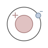 Liquid Hydrogen: Hydrogen liquefies at 20.27°K and remains liquid until 13.99°K. Recall that a "hard" superconductor has critical temperature above 14°K. EXAMPLE: the Niobium-Tin (Nb3Sn) alloy has critical temperature of 18°K which would work well with a bath of liquid Hydrogen (about 14° K). Space borne facilities might someday use water electrolysis to create quantities of gaseous hydrogen (H2) which could be liquefied via direct exposure to the extreme cold temperature (3° K) readily available in ambient space. Liquid Hydrogen: Hydrogen liquefies at 20.27°K and remains liquid until 13.99°K. Recall that a "hard" superconductor has critical temperature above 14°K. EXAMPLE: the Niobium-Tin (Nb3Sn) alloy has critical temperature of 18°K which would work well with a bath of liquid Hydrogen (about 14° K). Space borne facilities might someday use water electrolysis to create quantities of gaseous hydrogen (H2) which could be liquefied via direct exposure to the extreme cold temperature (3° K) readily available in ambient space.
|
 Liquid Oxygen: Same electrolysis which produces hydrogen from water also produces Oxygen gas (O2). It becomes liquid oxygen ("lox") between 54.36°K and 90.19°K which is much too warm for Nb3Sn to superconduct. Unless critical temp of some superconductor is significantly increased, lox probably won't used be used as a supercoolant; however, there will likely be some other use for lox on space vessels. Liquid Oxygen: Same electrolysis which produces hydrogen from water also produces Oxygen gas (O2). It becomes liquid oxygen ("lox") between 54.36°K and 90.19°K which is much too warm for Nb3Sn to superconduct. Unless critical temp of some superconductor is significantly increased, lox probably won't used be used as a supercoolant; however, there will likely be some other use for lox on space vessels. |
 Liquid Nitrogen: Nitrogen (N2) is in liquid from 63.15°K through 77.35°K. Like O2, N2 is plentiful on earth and not the best supercoolant. However, Nitrogen is an essential building block of amino and nucleic acids, essential to life on Earth and an essential part of the atmosphere. Though plentiful on earth, it's also plentiful on other planetary objects and might have to be "mined" from other planets/moons (i.e., Titan) for use in space vehicle's atmosphere. Perhaps available for liquefaction for use as onboard refrigerants if not for super-coolants. Liquid Nitrogen: Nitrogen (N2) is in liquid from 63.15°K through 77.35°K. Like O2, N2 is plentiful on earth and not the best supercoolant. However, Nitrogen is an essential building block of amino and nucleic acids, essential to life on Earth and an essential part of the atmosphere. Though plentiful on earth, it's also plentiful on other planetary objects and might have to be "mined" from other planets/moons (i.e., Titan) for use in space vehicle's atmosphere. Perhaps available for liquefaction for use as onboard refrigerants if not for super-coolants. |
| 10. COLLISION DETECTORS | |
Observe collisions; learn how to avoid them. Current synchrotrons have a scientific purpose; they accelerate particles to purposely create collisions; thus, particle detectors observe collided particles.. Accelerate particles to max momentum Thus, space borne detectors must alert operator to all collisions. 
Many earthbound accelerators use detectors for scientific experiments to investigate the internals of atomic scale objects. However, space borne detectors are not there to watch for experimental collisions but as a design feature to monitor and minimize collisions. | Particle detectors must monitor and record the results of particle collisions. With fewer particle collisions, more particles exit exhaust portal to contribute to exhaust momentum; thus, better propulsion performance. o Vertex detector - detects particle tracks. o Drift chamber - detects particle positions at several points along their tracks. Curved tracks reveal the momentum of the particle (related to its mass and velocity). o Cerenkov detector - sees radiation given off by rapidly moving particles and determines the particles' velocity Our notional spaceship would use its accelerator and its storage rings in a slightly different way. Since the ship's accelerator is part of the propulsion system, its purpose is to prepare high speed particles for discharge from the vehicle for an advantageous momentum exchange. Since momentum depends on mass as well as velocity, propulsion would gain from heavier particles being expelled; thus, the storage rings would concentrate on heavier ions and for ways to optimize their storage. MAJOR DISTINCTION: For g-force propulsion, spaceship accelerators need minimal particle collisions. OBJECTIVE: Maximize propulsion efficiency; thus, minimize collision loss. |
11. PARTICLE EJECTION
Ejection Kicker Magnets deflect a portion of the main particle beam out of the ring.
 | |||
|
Septum magnets guide particles toward the exhaust port to become part of the exhaust stream.
Combined force of all these near light speed particles cause constant momentum exchange to increase velocity of very large space ship ten meters per second for every second of powered flight. |
| ||

| SIDEBAR: EARLY PARTICLE ACCELERATOR STORIES | |||||
|---|---|---|---|---|---|
|
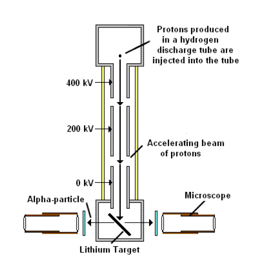
First Particle Accelerator was constructed by Cockcroft and Walton. It was a voltage multiplier with an intricate stack of capacitors connected to rectifying diodes used as switches. By opening and closing switches in proper sequence they created a potential of 800 kilovolts from a transformer of 200 kilovolts. They used this potential to accelerate protons down an evacuated tube eight feet long; they made history.
 John Cockcroft was eldest of five sons of a Yorkshire miller. He won a scholarship to study math at Manchester Univ but become greatly interested in atomic physics after reading work by J.J. Thompson and Ernest Rutherford (then at Manchester). His studies were interupted by WWI, he was sole survivor of a unit caught in bitter fighting on Western Front. After completing a EE degree from Manchester, he joined Metropolitan Vickers Company and eventaully went to Cambridge to improve his math. He again met Rutherford who took him into famous Cavendish Lab. John Cockcroft was eldest of five sons of a Yorkshire miller. He won a scholarship to study math at Manchester Univ but become greatly interested in atomic physics after reading work by J.J. Thompson and Ernest Rutherford (then at Manchester). His studies were interupted by WWI, he was sole survivor of a unit caught in bitter fighting on Western Front. After completing a EE degree from Manchester, he joined Metropolitan Vickers Company and eventaully went to Cambridge to improve his math. He again met Rutherford who took him into famous Cavendish Lab. Ernest Thomas Sinton Walton was born in County Waterford, Ireland. The son of a Methodist minister, he went to Methodist College, Belfast in 1915 where he excelled in math and science. In 1926, he graduated from Trinity College Dublin. Ernest Thomas Sinton Walton was born in County Waterford, Ireland. The son of a Methodist minister, he went to Methodist College, Belfast in 1915 where he excelled in math and science. In 1926, he graduated from Trinity College Dublin.In 1927, he went to Cambridge University to work for Lord Rutherford at the Cavendish Lab. Walton was awarded a PhD in 1931. To split the atom, Cockcroft and Walton (C&W) needed a "high voltage generator" to generate a high speed, proton stream. Therefore, C&W were compelled to co-invent the high voltage generator. During not so prosperous times, they scoured the British countryside for discarded glass sight tubes from petrol pumps which they stacked to form the acceleration tube. They used this apparatus in 1932 to accelerate protons for the very first time. This was a remarkable feat, but this achievement alone would not have secured their place in science history which they now hold. C&W were the first scientists to literally split an atom into two parts. By stripping electrons from hydrogen atoms, they used the high electrical voltage to accelerate numerous proton ions as a stream of near light speed protons. They were the first to "split" the atom by bombarding lithium with a proton stream. Thus, a very few of the billions of protons encountered a lithium atom and caused it to break into two helium atoms. Thus, they were able to transmute lithium into helium. After this Nobel winning accomplishment, C&W both went on to distinguished scientific careers.
|
Electrostatic Accelerators. The first particle accelerators used a single static high voltage to accelerate charged particles. Widely used today, they are more suited to lower energy studies due to their practical voltage limit of about 30 MV. Several such devices can be connected in series to further accelerate the particles.
Linear Accelerators (LINACs) use oscillating electric fields to accelerate particles in a straight line. LINACs perform much better than electrostatic accelerators; HOWEVER, they have obvious limits. Their finite distance limits their acceleration potential. Particles enter one end, travel a limited distance; finally, exit or impact at the other end. Acceleration could greatly increase if particles could keep going.
Cyclotrons were the earliest operational circular accelerators; a cyclotron is a large dipole magnet with a constant magnetic field. In such a field, a radio frequency (RF) power source drives the charged particles to orbit at a constant “cyclotron frequency”. The particles start circling near the center of the magnet d spiral outwards as they gain energy; they eventually exit at the outer edge as they attain their maximum energy.
Like LINACs, cyclotrons have their own limits; increasing particle's velocity increased their turn radius (resulting in particle's spiraling path, typical of cyclotron); so, they must soon exit the device. However, both LINACs and cyclotrons are now used as "feeders" for much more powerful accelerators.
Cyclic Accelerators can achieve much more energy then cyclotrons. In cyclic accelerators, particles orbit in a circular beam guide until they achieve desired energy. Cyclic accelerators use electromagnets to bend particle path.
Synchrotron is an evacuated beam pipe encased in hundreds of magnets; synchrotron design assigns several functions to distinct magnet groups. It uses RF power sources to accelerate ions to near light speed, c, in a constant radius ring. RF amplitude cycles cause the particles to form “bunches”, which regularly eject to an external beam. As an advanced, cyclic particle accelerator, it synchronizes the magnetic fields (turns the particles to circulate in numerous orbits) and the electric fields (to accelerate the particles) with the traveling particle beam. While the overall shape is circular, the synchrotron is divided into many straight sections of beam pipe between specified bending magnets. In these straight sections, look for other devices such as RF cavities, focusing magnets, ejectors, injectors, detectors, etc. Synchrotron’s overall placement of devices is often called a “lattice”; the lattice design has developed into an entire discipline, "beam physics" or "beam optics". Storage Ring. Some applications must store beams of high energy particles for some time (high vacuum technology enables storage for many hours) without further acceleration. A storage ring can store multiple beams; even counter rotating beams (moving in opposite directions). It is customary to first accelerate the beams to the desired energy, and then store them in storage rings, essentially synchrotron rings with magnets but without RF cavities. | ||||
 Cockcroft and Walton led the Cavendish effort to build the first effective particle accelerator. However, they were one of five scientific teams vying to accomplish this impressive task.
|
Simpler Synchrotron Considerations:
| ||||

| COMPONENT | ACCELERATOR FUNCTION | LEVERAGE SPACE ENVIRONMENT |
|---|---|---|
| PLASMA SOURCES | Transform water into ions for acceleration. | o Export water from terrestrial . o Import ices from extraterrestrial comets |
| PARTICLE INJECTION | Puts ions into wave guide. | Rate determined by ship's mass. |
| BEAM PIPE PATHWAY | vacuum tube provides path for particle beam. | Design determined by size/shape of ship. |
| MAGNETIC FIELDS | steer and focus the particle beam. | Design determined by size/shape of ship. |
| RF CAVITIES | generate microwaves for the particles to ride. | Required for particle acceleration. |
| SUPERCONDUCTION | Save enormous energy | Required for magnet practicality. |
| STORAGE RINGS | orbit particles until extraction. | Key design factor. |
| VACUUM SYSTEM | keeps wave guide completely clear. | Plenty of vacuum in deep space. |
| COOLING SYSTEM | removes heat generated by equipment. | Plenty of cold in space (4° K); can make liquid hydrogen from water supplies. |
| COLLISION DETECTION | examines radiation from particles colliding with each other and with walls of wave guide. | Needed for efficiency as well as safety concerns. Not easy to repair wave guide, even harder during powered flight. |
| PARTICLE EJECTION | Puts ions into exhaust ports. | Rate determined by efficiency. |
| VOLUME 0: ELEVATIONAL |
|---|
| VOLUME I: ASTEROIDAL |
| VOLUME II: INTERPLANETARY |
| VOLUME III: INTERSTELLAR |
posted by JimODell at 2:06 AM
![]()
![]()

.png)
1 Comments:
James *Jason* Wentworth (e-mail: blackshire@alaska.net )
Hello Jim,
I am a lifelong space exploration and exploitation advocate, and I read—and have occasionally contributed articles to—Paul Gilster’s Centauri Dreams blog www.centauri-dreams.org . He is intrigued by your propulsion “Thought Experiments” (such as your particle accelerator engines: http://starsdestination.blogspot.com/2013/02/accelerators-storage-rings.html ), as am I. (If you would be interested in writing an article for his blog—which is read by many researchers in the interstellar [and interplanetary] spaceflight community—I think he would be interested in publishing it [although I can’t speak for him, of course].) Also, I just came across your ion-drive thought experiment http://starsdestination.blogspot.com/2011/10/vasimr.html , and it raises four questions, which touch upon your “ion engines as injectors into a larger engine” idea (Paul couldn’t answer my questions, but perhaps you can). They are as follows:
[1] Do large, up-scaled ion engines (like the big, “starship-size” one depicted by Chesley Bonestell, in Willy Ley’s 1964 book “Beyond the Solar System” [see: http://www.flickriver.com/photos/57440551@N03/24070579816/ and www.pinterest.com/pin/537617274238717827/ ]) have any advantages (besides *not* having the burden of extra mass of the numerous pipes, wiring harnesses, and propellant pipes of numerous clustered small ion thrusters) over clusters of smaller ones? (Such a large, gridded ion thruster—or such a big Hall Effect thruster, perhaps one having numerous concentric, “nested” ‘thrust ring slots’—might provide room for extra sets of accelerator grids [one 1960s-vintage Glenn L. Martin Company cesium ion thruster had five grids!] or, for a big Hall Effect thruster, extra—or longer—accelerator coils.)
[2] Could sodium and/or sulfur be used as ion thruster fuels? (Both appear to be easily ionize-able, and they have pretty high atomic masses; also, both are readily accessible from Mercury, Io, and/or our Moon. Mercury also has plenty of heavy metals, such as cesium and [appropriately for that planet! :-) ] mercury, both of which are also effective ion engine propellants.)
[3] Looking at older mercury-fueled and cesium-fueled ion engines, I saw that their exhaust beam neutralizers weren’t electron guns, but were simple filaments. Could the problems of metal contamination of the spacecraft (which was one of the reasons why cesium and mercury fell out of favor as ion engine propellants) be eliminated (or at least greatly reduced) if such engines employed electron gun beam neutralizers instead of filaments? (If so, Mercury—and probably also our Moon and some asteroids [especially metallic ones]—contain large amounts of mercury and cesium.) Also:
[4] I found that the 1973 Soviet conference on CETI (Communication with Extra-Terrestrial Intelligence) included papers about studies of ion-drive interstellar probes. They concluded that with then-current technology, ion-drive starprobes capable of reaching 5% of c, the speed of light, were feasible (such probes, which would depart from Earth orbit, would be about the size of a Saturn rocket). If that was feasible with 1973 technology, what might be feasible with today’s ion propulsion (and Hall Effect thruster) technology?
Many thanks in advance for your help!
-- Jason
Post a Comment
<< Home